| 产品特性:功率稳定 | 加工定制:否 | 品牌:梓冠 |
| 型号:ZG | 种类:配件组件 | 波段范围:1530—1570 nm or 1270nm—1330 nm |
| 运转方式:连续式 | 激励方式:电激励式 | 工作物质:半导体 |
| 光路径:透过型外光路 | 输出形式:功率型 | 传输信号:单电源型 |
| 速度:高速 | 通道:多通道 | 输出波长:1530—1570 nm or 1270nm—1330 nmnm |
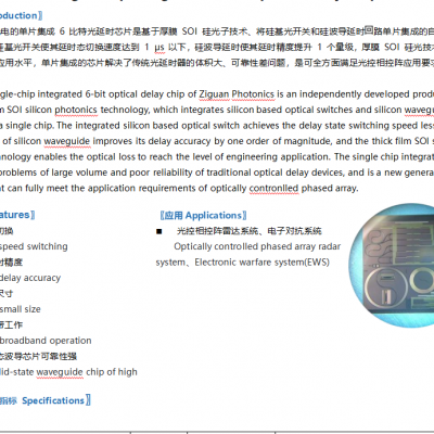
〖简介Introduction〗
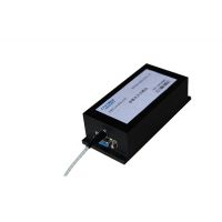
梓冠光电的单片集成 6 比特光延时芯片是基于厚膜 SOI 硅光子技术、将硅基光开关和硅波导延时路单片集成的自主研发产品。集成的硅基光开关使其延时态切换速度达到 1 μs 以下,硅波导延时使其延时精度提升 1 个量级,厚膜 SOI 硅光技术使其光损耗达到工程应用水平,单片集成的芯片解决了传统光延时器的体积大、可靠性差问题,是可全方面满足光控相控阵应用要求的新一代产品。
The single-chip integrated 6-bit optical delay chip of Ziguan Photonics is an independently developed product based on thick film SOI silicon photonics technology, which integrates silicon based optical switches and silicon waveguide delay circuits on a single chip. The integrated silicon based optical switch achieves the delay state switching speed less than 1 μs, the delay of silicon waveguide improves its delay accuracy by one order of magnitude, and the thick film SOI silicon optical technology enables the optical loss to reach the level of engineering application. The single chip integrated chip solves the problems of large volume and poor reliability of traditional optical delay devices, and is a new generation product that can fully meet the application requirements of optically contronlled phased array.
〖特性Features〗
n 高速切换
High speed switching
n 高延时精度
High delay accuracy
n 超小尺寸
Ultra-small size
n 超宽带工作
Ultra-broadband operation
n 全固态波导芯片可靠性强
All solid-state waveguide chip of high
〖应用Applications〗
n 光控相控阵雷达系统、电子对抗系统
Optically controlled phased array radar system、Electronic warfare system(EWS)
〖主要性能指标 Specifications〗
性能指标 Parameter | 单位 Unit | 典型值 Typical value | 备注 Notes |
延时位数 Delay bits | / | 6 | 可定制 Can be customized |
最小延时步进 Min.step-delay | ps | 59.2 | 可定制 Can be customized |
可调节延时量 Adjustable max.delay | ps | 3729.6 | |
延时偏差 Delay deviation | ps | ≤±0.5 | ≤±1@max |
延时切换时间 Delay switching time | ?s | ≤1 | |
插入损耗 Insertion loss | dB | 14 | |
各延时态损耗差异 Delay state loss difference | dB | ±0.5 | |
波损耗 Return loss | dB | 45 | |
芯片尺寸 Chip dimension | mm | 22×10×0.7 |
〖电管脚定义 Pin definition〗

图 1 单个 2×2 光开关光信号输入输出端口示意
Figure 1 Diagram of A single 2×2 optical switch optical signal input and output ports
〖2×2 光开关(图 1)的“交叉”、“直通”传输状态定义如下〗
〖The "Cross" and "Bar" transmission states of the 2×2 optical switch (Figure 1) is defined as follows〗
“交叉”状态(Cross 态):从输入 A 端输入,输出端 D 有光信号输出,输出端 C 没有光信号输出时,即为”交叉“态(A→D);类似定义,从输入端 B 输入,输出端 C 光信号输出,输出端 D 没有光信号输出,也为”交叉“态(B→C)。
“直通”态(bar 态):从输入端 A 处输入,输出端 C 有输出光信号,输出端 D 没有光信号输出时,即为”直通“态(A→C);类似定义,从输入端 B 输入,输出端 D 有光信号输出,输出端 C 没有光信号输出,也为“直通”态(B→àD。
Cross state: When input is from input A, output D has an optical signal output, and output C has no optical signal output, it is called the "cross" state (A → D);Similarly, when input is from input B, output C has an optical signal output, and output D has no optical signal output, it is also called the "cross" state (B → C).
The "Bar" state (bar state): When input is from input A, output C has an output optical signal, and output D has no optical signal output, it is called the "bar" state (A → C). Similarly, when input is from input B, output D has an optical signal output, and output C has no optical signal output, it is also called the "bar" state (B → D).
〖6bit 可调延时器芯片 PAD 尺寸为 150μm×150μm,PAD 中心间距为 200μm,各 PAD 定义如下表〗
The PAD size of the 6-bit adjustable delay device chip is 150μm×150μm. and the center distance of the PAD is 200 μ m. The definition of each PAD is as follows:
序号No. | 名称Name | 描述 Description | 序号 No. | 名称 ame | 描述 Description |
1 | DMY | dummy | 19 | CH5+C | 开关 5 正极 cross 态 |
2 | DMY | dummy | 20 | CH5- | 开关 5 负极 |
3 | DMY | dummy | 21 | CH5+B | 开关 5 正极 bar 态 |
4 | DMY | dummy | 22 | CH6+C | 开关 6 正极 cross 态 |
5 | DMY | dummy | 23 | CH6- | 开关 6 负极 |
6 | DMY | dummy | 24 | CH6+B | 开关 6 正极 bar 态 |
7 | CH4+B | 开关 1 正极 bar 态 | 25 | CH7+C | 开关 7 正极 cross 态 |
8 | CH4- | 开关 1 负极 | 26 | CH7- | 开关 7 负极 |
9 | CH4+C | 开关 1 正极 cross 态 | 27 | CH7+B | 开关 7 正极 bar 态 |
10 | CH3+B | 开关 2 正极 bar 态 | 28 | CH8+ | To be defined |
11 | CH3- | 开关 2 负极 | 29 | CH8- | To be defined |
12 | CH3+C | 开关 2 正极 cross 态 | 30 | CH8+ | To be defined |
13 | CH2+B | 开关 3 正极 bar 态 | 31 | DMY | dummy |
14 | CH2- | 开关 3 负极 | 32 | DMY | dummy |
15 | CH2+C | 开关 3 正极 cross 态 | 33 | DMY | dummy |
16 | CH1+B | 开关 4 正极 bar 态 | 34 | DMY | dummy |
17 | CH1- | 开关 4 负极 | 35 | DMY | dummy |
18 | CH1+C | 开关 4 正极 cross 态 | 36 | DMY | dummy |
〖延时量和光开关传输状态对应关系Correspondence between delay amount&optical switch transmission state〗
图 2 6bit 可调光延时器拓扑示意
Figure 2 Diagram of 6 Bit adjustable optical delay device
表 1 延时量和光开关传输状态的对应关系
Form 1 Correspondence between delay amount&optical switch transmission state
延时量 Delay amount (*59.2ps) | 光开关 Optical switch | 延时量 Delay amount (*59.2ps) | 光开关 Optical switc | ||||||||||||
1 | 2 | 3 | 4 | 5 | 6 | 7 | 1 | 2 | 3 | 4 | 5 | 6 | 7 | ||
0 | C | C | C | C | C | C | C | 32 | B | B | C | C | C | C | C |
1 | C | C | C | C | C | B | B | 33 | B | B | C | C | C | B | B |
2 | C | C | C | C | B | B | C | 34 | B | B | C | C | B | B | C |
3 | C | C | C | C | B | C | B | 35 | B | B | C | C | B | C | B |
4 | C | C | C | B | B | C | C | 36 | B | B | C | B | B | C | C |
5 | C | C | C | B | B | B | B | 37 | B | B | C | B | B | B | B |
6 | C | C | C | B | C | B | C | 38 | B | B | C | B | C | B | C |
7 | C | C | C | B | C | C | B | 39 | B | B | C | B | C | C | B |
8 | C | C | B | B | C | C | C | 40 | B | B | B | B | C | C | C |
9 | C | C | B | B | C | B | B | 41 | B | B | B | B | C | B | B |
10 | C | C | B | B | B | B | C | 42 | B | B | B | B | B | B | C |
11 | C | C | B | B | B | C | B | 43 | B | B | B | B | B | C | B |
12 | C | C | B | C | B | C | C | 44 | B | B | B | C | B | C | C |
13 | C | C | B | C | B | B | B | 45 | B | B | B | C | B | B | B |
14 | C | C | B | C | C | B | C | 46 | B | B | B | C | C | B | C |
15 | C | C | B | C | C | C | B | 47 | B | B | B | C | C | C | B |
16 | C | B | B | C | C | C | C | 48 | B | C | B | C | C | C | C |
17 | C | B | B | C | C | B | B | 49 | B | C | B | C | C | B | B |
18 | C | B | B | C | B | B | C | 50 | B | C | B | C | C | B | C |
19 | C | B | B | C | B | C | B | 51 | B | C | B | C | C | C | B |
20 | C | B | B | B | B | C | C | 52 | B | C | B | B | B | C | C |
21 | C | B | B | B | B | B | B | 53 | B | C | B | B | B | B | B |
22 | C | B | B | B | C | B | C | 54 | B | C | B | B | C | B | C |
23 | C | B | B | B | C | C | B | 55 | B | C | B | B | C | C | B |
24 | C | B | C | B | C | C | C | 56 | B | C | C | B | C | C | C |
25 | C | B | C | B | C | B | B | 57 | B | C | C | B | C | B | B |
26 | C | B | C | B | B | B | C | 58 | B | C | C | B | B | B | C |
27 | C | B | C | B | B | C | B | 59 | B | C | C | B | B | C | B |
28 | C | B | C | B | C | C | C | 60 | B | C | C | C | B | C | C |
29 | C | B | C | C | B | C | C | 61 | B | C | C | C | B | B | B |
30 | C | B | C | B | C | B | C | 62 | B | C | C | C | C | B | C |
31 | C | B | C | B | C | C | B | 63 | B | C | C | C | C | C | B |
注:B 为光开关 bar 状态,C 为光开关 cross 状态。
Note:B indicates the bar state of the optical switch,C indicates the cross state of optical switch
〖芯片尺寸(单位:mm)Chip dimension(Unit:mm)〗